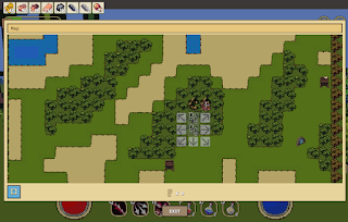
Stitching tiles to neighbor tiles at different altitudes.
Suppose you have a 2D tilemap grid of altitudes, and mapped tile types to each coordinate based on the altitude generated.
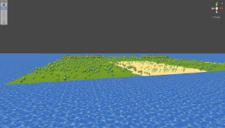
What if you wanted to display this in 3D? With the actual altitude set at each tile with full scale mountains?
Recently, I set out to do just that. Initially I just put terrain objects down at the grid coordinates in 3D space, but kept all of the height values the same.
This results in an overall flat world. Each individual tile can have a heightmap that adds bumps or hills, but there is no global altitude being applied.
So, what if we want to add our global altitude to our tiles? Instead of placing every tile at height 0, lets set it to the altitude generated. As you can imagine, this creates a pretty immediate problem:
When a tile is a different altitude than its neighbors, a gap forms between the edges. This is bad for obvious reasons, you don't want players falling off the world in to the abyss of -y coordinates.
How do we solve this? We need to "stitch" the edges and corners of our tile to all of our neighbors, regardless of what altitudes they have, and we want to do it in a smooth way. We don't want to just set values along the edges, which would result in cliffs everywhere there is a tile border.
Let's start with a little background on what we are working with. What exactly is a 'tile' and how do we adjust the height/shape of it?
A tile, in my case, is a Unity gameObject with a Terrain component attached. It has a 3D coordinate (x, y, z), where the Y value determines its vertical position, and x and z determine the two horizontal directions (if you are standing on the terrain, z goes toward and away from you, x goes left and right).
But this coordinate determines the position of the entire tile object, so setting it moves all points in the terrain to their relative positions around the center of the tile. To adjust the shape of the tile itself, we use a heightmap texture.
A heightmap just has greyscale pixels whose values (ranging from 0 to 1, black to white, low to high) represent the height of the terrain at that point.
With no idea how I was going to solve all points on the terrain, I figured the best first stab would be to worry about one edge in one direction. And instead of placing my terrain tile position at the altitude, I will simply set the altitude on the heightmap for each point on my terrain.
So if we only consider tiles to the north and south of our position, its pretty simple to see we need to calculate the slope. Since there are 2 different slopes to worry about, north and south, we should calculate from the center of our tile. Points above the center will be set to the north slope, and points below the center will be set to the south slope.
In this test run, the top tile has an altitude of .5, while the bottom tile has an altitude of 0. Each cell represents a pixel on the heightmap, and is shaded accordingly. (We aren't worrying about neighbors to the left or right)
The result:
As you can see, we do have a nice slope in one direction. However, each x coordinate has a slightly different slope, resulting in "strips" of terrain with gaps in between the left and right edges.
Here you can see it in the data, notice the top and bottom edge values match for each neighboring tile, but the left and right are off.
From now on, we will use these data grids to iterate our approaches, since the data is clearly represented. Our goal is to have the values on all grid edges match the neighboring tile's edge or corner value, in all directions, regardless of altitudes.
I suppose the next step is to try the same method for the left and right direction.
Well we hit our goal, or at least what we thought was the goal. Notice all edges now have matching values! But the corners are very far off... and those sharp color changes cant be good.
Yea.. nope. That's no good.
So perhaps we need to add the corner slope as well for all 4 of our corner neighbors, and then march along the diagonal lines from the center of our tile to the corners by that slope.
Well, now the corners are fixed, but clearly something is still missing. We still have these extreme value changes along the corner lines in some cases.
We need a way to blend each pixel in these triangles, but what are we blending between and how?
Well, there are 3 points that we have concrete values for.
- The middle of our tile
- The edge point along the y or x axis where we meet with our adjacent neighbor's edge.
- The corner point along the diagonal axis where we meet with our corner neighbor's corner.
To get a nice blend between these corners, it seems we should assign a 'weight' value for each corner on each pixel based on the distance between the pixel and each corner. This will give us a normalized value based on the pixel's coordinate and the values at each corner.
Here are the weight values displayed in the grid for each respective pixel in the triangle along the bottom edge and right corner:
While it appears slightly off, since only the first triangle representing the edge weights has full '1.0' weights, it turns out to be ok because we assign the diagonals of our tile weights to be 1.0 for the corner slopes.
So now we just assign the sum of the result of each corner value multiplied by its respective weight to each pixel. And we're good to go!
As you can see every border and corner has a smooth transition in to the neighboring tile's values.
And in game it looks seamless!


Comments
Post a Comment